After inputting the blank parameters, querying the material model, selecting the fixture model, selecting the tool model, and setting the workpiece coordinate system origin, return to the edit main menu, create a process table file, and store the process parameters. Previous page next page Edge Banding,Pvc Edge Banding Tape,Plastic Edge Strip,T Edge Banding Wuxi Jierui Changkun New Material Technology Co., Ltd , https://www.jrck-plastic.com
4) Select tool
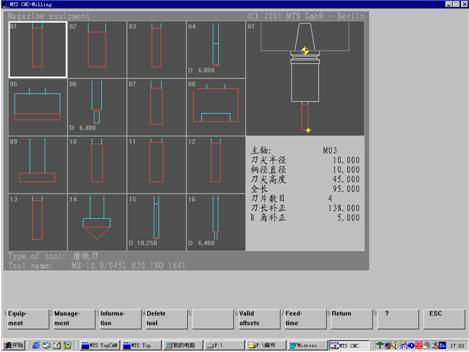
Select Tool Reference → Tool Library Equipment → Equipment → Select Tool Menu, open the Rotary Turret dialog box, and then select the tool type and tool model for the corresponding tool number. 16 knives can be installed in the rotating turret (Fig. 3). Each knives has its specified tool code. Due to the different structural dimensions of each tool, the tool must be compensated after the tool is selected. Press Valid in the menu. The offsets button completes tool compensation for each selected tool. 
Figure 3 Milling table rotary turret
5) Set the workpiece coordinate system origin
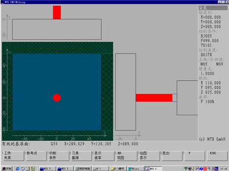
The workpiece coordinate system is set according to the principle of the reference coincidence. Generally, the tool of the tool code T01 is used as the reference tool, and the origin of the workpiece coordinate system is set by the tool setting operation of the reference tool. For the symmetric workpiece, the center of symmetry of the workpiece is taken as the X axis and The origin of the Y-axis; for the asymmetric workpiece, the intersection of the left side of the workpiece and the front of the workpiece is taken as the origin of the X-axis and the Y-axis, and the origin of the Z-axis is generally set at the upper surface position of the workpiece. In this example, the intersection of the left and right center lines of the part drawing and the front and rear center lines is taken as the origin of the X-axis and Y-axis of the workpiece coordinate system. After setting the origin of the workpiece coordinate system, select the setting reference menu, the reference record will be displayed in the G54 block, where the address characters X289.029, Y134.305, Z89 represent the coordinate values ​​of the workpiece coordinate system origin in the machine coordinate system ( Figure 4).
Set the workpiece coordinate system origin method, select the tool replacement menu, call the No. 1 knife as the reference knife, operate through the keyboard button, set the tool tip position to the origin of the workpiece coordinate system, and then set the X, Y, Z coordinate values ​​to zero respectively. , that is, the origin of the workpiece coordinate system is set.
The function of the arrow keys in the keyboard:
Right arrow key →, the tool moves in the positive direction of the X axis;
Left arrow key â†, the tool moves in the negative direction of the X axis;
The up arrow key ↑, the tool moves in the positive direction of the Z axis;
Press the down arrow key ↓ and the tool moves in the negative direction of the Z axis;
Page Up button, the tool moves in the positive direction of the Y axis;
End key, the tool moves in the negative direction of the Y axis. 
Figure 4 Setting the workpiece coordinate system origin
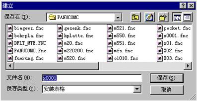
Select the installation form → create menu, open the Create File dialog box (Figure 5), enter the file name, press the save button to build the process form file, and the subsequent machining program is also stored in the process form file.
Select Program Edit → Select program menu, open the program selection dialog box, enter the name of the process table file, and store the selected CNC system, workpiece blank size, workpiece material model, fixture model, tool model and design in the opened process sheet file. The workpiece coordinate system parameters are determined, and then the machining program is written in the process table file. 
Figure 5 Create Program Dialog